목차: 01-Overview (Link)
이전 글: 13-Shader Modules on Graphics Pipeline (Link)
다음 글: 15-Render Passes (Link)
기존의 Graphics APIs(OpenGL 등)는 Graphics Pipeline 중 Fixed Functions 부분에 해당하는 Step에 Default Setting을 제공한다. 결과적으로 특별한 설정을 해주지 않아도 Vertex Shader, Fragment Shader 만 작성하면 Graphics Pipeline을 사용할 수 있다는 의미이다. 하지만, Vulkan API의 경우 Fixed Function의 Default Setting이란 것이 존재하지 않는다. 그래서 모든 Fixed Function에 대한 설정을 해야만 한다. 이번 장에서는 Graphics Pipeline의 Fixed Function 설정을 하기 위한 코드를 작성할 예정이다. 앞에 작성한 글과 같이 여러 개의 Sub-Section을 통해서 코드를 설명한다. 아래 코드 1은 Fixed Function Setting을 설정하는 코드이다.
코드 1: Fixed Function 함수 설정 추가 코드
#include <iostream>
#include <stdexcept>
#include <functional>
#include <cstdlib>
#include <util_init.hpp>
#include <set>

#define APP_SHORT_NAME "mkVulkanExample"

#define MK_GET_INSTANCE_PROC_ADDR(inst, entrypoint)												\
{																								\
	fp##entrypoint = (PFN_vk##entrypoint)vkGetInstanceProcAddr(instance, "vk" #entrypoint);		\
	if (fp##entrypoint == NULL) {																\
		std::cout << "vkGetDeviceProcAddr failed to find vk" #entrypoint;						\
		exit(-1);																				\
	}																							\
}


class mkTriangle{
	public:
		void run(){
			...
		}

	private:
		void initVulkan(){
			...
		}

		void mainLoop(){
		}

		void cleanup(){
			LOGI("MK: cleanup Function");

			//MK: (코드 1-13) Pipeline Layout 제거
			vkDestroyPipelineLayout(device, pipelineLayout, NULL);

			for(int i = 0; i < swapChainImageViews.size(); i++){
				vkDestroyImageView(device, swapChainImageViews[i], NULL);
			}
			vkDestroySwapchainKHR(device, swapChain, NULL);
			vkDestroyDevice(device, NULL);
			vkDestroySurfaceKHR(instance, surface, NULL);
			vkDestroyInstance(instance, NULL);
		}

		void createInstance(){
			...

		}

		void createSurface(){
			...
		}

		void pickPhysicalDevice(){
			...
		}

		void printPhysicalDeviceInfo(VkPhysicalDevice device){
			...
		}

		void searchQueue(){
			...
                }

		void createLogicalDevice(){
			...
		}

		void createSwapChain(){
			...
		}

		void createImageViews(){
			...
		}

		void createGraphicsPipeline(){

			LOGI("MK: (Begin) createGraphicsPipeline Function");

			static const char *vertShaderText=
			"#version 450\n"
			"#extension GL_ARB_separate_shader_objects : enable\n"
			"vec2 positions[3] = vec2[](vec2(0.0, -0.5), vec2(0.5, 0.5), vec2(-0.5, 0.5));\n"
			"vec3 colors[3] = vec3[](vec3(1.0, 0.0, 0.0), vec3(0.0, 1.0, 0.0), vec3(0.0, 0.0, 1.0));\n"
			"layout(location = 0) out vec3 fragColor;\n"
			"void main() {\n"
			"gl_Position = vec4(positions[gl_VertexIndex], 0.0, 1.0);\n"
			"fragColor = colors[gl_VertexIndex];}\n";

			static const char *fragShaderText=
			"#version 450\n"
			"#extension GL_ARB_separate_shader_objects : enable\n"
			"layout(location = 0) in vec3 fragColor;\n"
			"layout(location = 0) out vec4 outColor;\n"
			"void main() {\n"
			"outColor = vec4(fragColor, 1.0);}\n";

			std::vector<unsigned int> vtxSpv;
			std::vector<unsigned int> fragSpv;

			init_glslang();

			bool retVal;
			retVal = GLSLtoSPV(VK_SHADER_STAGE_VERTEX_BIT, vertShaderText, vtxSpv);
			assert(retVal == true);
			LOGI("\tMK: Vertex Code is converted to SPV");

			retVal = GLSLtoSPV(VK_SHADER_STAGE_FRAGMENT_BIT, fragShaderText, fragSpv);
			assert(retVal == true);
			LOGI("\tMK: Fragment Code is converted to SPV");

			VkShaderModule vertShaderModule;
			VkShaderModule fragShaderModule;

			VkShaderModuleCreateInfo createInfo = {};
			createInfo.sType = VK_STRUCTURE_TYPE_SHADER_MODULE_CREATE_INFO;
			createInfo.pNext = NULL;
			createInfo.flags = 0;
			createInfo.codeSize = vtxSpv.size() * sizeof(unsigned int);
			createInfo.pCode = vtxSpv.data();

			VkResult result = vkCreateShaderModule(device, &createInfo, NULL, &vertShaderModule);
			assert(result == VK_SUCCESS);
			LOGI("\tMK: Vertex Module is created\n");

			createInfo.sType = VK_STRUCTURE_TYPE_SHADER_MODULE_CREATE_INFO;
			createInfo.pNext = NULL;
			createInfo.flags = 0;
			createInfo.codeSize = fragSpv.size() * sizeof(unsigned int);
			createInfo.pCode = fragSpv.data();

			result = vkCreateShaderModule(device, &createInfo, NULL, &fragShaderModule);
			assert(result == VK_SUCCESS);
			LOGI("\tMK: Fragment Module is created\n");

			shaderStages[0].sType = VK_STRUCTURE_TYPE_PIPELINE_SHADER_STAGE_CREATE_INFO;
			shaderStages[0].pNext = NULL;
			shaderStages[0].flags = 0;
			shaderStages[0].stage = VK_SHADER_STAGE_VERTEX_BIT;
			shaderStages[0].module = vertShaderModule;
			shaderStages[0].pName = "main";
			shaderStages[0].pSpecializationInfo = NULL;

			shaderStages[1].sType = VK_STRUCTURE_TYPE_PIPELINE_SHADER_STAGE_CREATE_INFO;
			shaderStages[1].pNext = NULL;
			shaderStages[1].flags = 0;
			shaderStages[1].stage = VK_SHADER_STAGE_FRAGMENT_BIT;
			shaderStages[1].module = fragShaderModule;
			shaderStages[1].pName = "main";
			shaderStages[1].pSpecializationInfo = NULL;

			//MK: (코드1-1) VkPipelineVertexInputStateCreateInfo Struct 코드 생성 및 변수 값 설정
			VkPipelineVertexInputStateCreateInfo vertexInputInfo = {};
			vertexInputInfo.sType = VK_STRUCTURE_TYPE_PIPELINE_VERTEX_INPUT_STATE_CREATE_INFO;
			vertexInputInfo.pNext = NULL;
			vertexInputInfo.flags = 0;
			vertexInputInfo.vertexBindingDescriptionCount = 0;
			vertexInputInfo.pVertexBindingDescriptions = NULL;
			vertexInputInfo.vertexAttributeDescriptionCount = 0;
			vertexInputInfo.pVertexAttributeDescriptions = NULL;

			//MK: (코드 1-2) Input Assembly를 설정하는 부분
			VkPipelineInputAssemblyStateCreateInfo inputAssembly = {};
			inputAssembly.sType = VK_STRUCTURE_TYPE_PIPELINE_INPUT_ASSEMBLY_STATE_CREATE_INFO;
			inputAssembly.pNext = NULL;
			inputAssembly.flags = 0;
			inputAssembly.topology = VK_PRIMITIVE_TOPOLOGY_TRIANGLE_LIST;
			inputAssembly.primitiveRestartEnable = VK_FALSE;

			//MK: (코드 1-3) Viewports를 설정하는 부분
			VkViewport viewport = {};
			viewport.x = 0.0f;
			viewport.y = 0.0f;
			viewport.width = (float) selectedExtent.width;
			viewport.height = (float) selectedExtent.height;
			viewport.minDepth = 0.0f;
			viewport.maxDepth = 1.0f;

			//MK: (코드 1-4) Scissors을 설정하는 부분
			VkRect2D scissor;
			scissor.offset = {0, 0};
			scissor.extent = selectedExtent;

			//MK: (코드 1-5) Viewports/Scissors 설정 저장
			VkPipelineViewportStateCreateInfo viewportState = {};
			viewportState.sType = VK_STRUCTURE_TYPE_PIPELINE_VIEWPORT_STATE_CREATE_INFO;
			viewportState.pNext = NULL;
			viewportState.flags = 0;
			viewportState.viewportCount = 1;
			viewportState.pViewports = &viewport;
			viewportState.scissorCount = 1;
			viewportState.pScissors = &scissor;

			//MK: (코드 1-6) Rasterizer 설정 코드
			VkPipelineRasterizationStateCreateInfo rasterizer = {};
			rasterizer.sType = VK_STRUCTURE_TYPE_PIPELINE_RASTERIZATION_STATE_CREATE_INFO;
			rasterizer.pNext = NULL;
			rasterizer.flags = 0;
			rasterizer.depthClampEnable = VK_FALSE;
			rasterizer.rasterizerDiscardEnable = VK_FALSE;
			rasterizer.polygonMode = VK_POLYGON_MODE_FILL;
			rasterizer.lineWidth = 1.0f;
			rasterizer.cullMode = VK_CULL_MODE_BACK_BIT;
			rasterizer.frontFace = VK_FRONT_FACE_CLOCKWISE;
			rasterizer.depthBiasEnable = VK_FALSE;
			rasterizer.depthBiasConstantFactor = 0.0f;
			rasterizer.depthBiasClamp = 0.0f;
			rasterizer.depthBiasSlopeFactor = 0.0f;

			//MK: (코드 1-7) Multisample Setting 코드
			VkPipelineMultisampleStateCreateInfo multisampling = {};
			multisampling.sType = VK_STRUCTURE_TYPE_PIPELINE_MULTISAMPLE_STATE_CREATE_INFO;
			multisampling.pNext = NULL;
			multisampling.flags = 0;
			multisampling.pSampleMask = NULL;
			multisampling.rasterizationSamples = VK_SAMPLE_COUNT_1_BIT;
			multisampling.sampleShadingEnable = VK_FALSE;
			multisampling.alphaToCoverageEnable = VK_FALSE;
			multisampling.alphaToOneEnable = VK_FALSE;
			multisampling.minSampleShading = 0.0f;

			//MK: (코드 1-8) Color Blending Setting 코드
			VkPipelineColorBlendAttachmentState colorBlendAttachment = {};
			colorBlendAttachment.colorWriteMask = VK_COLOR_COMPONENT_R_BIT | VK_COLOR_COMPONENT_G_BIT | VK_COLOR_COMPONENT_B_BIT | VK_COLOR_COMPONENT_A_BIT;
			colorBlendAttachment.blendEnable = VK_FALSE;
			//MK: 나머지 값은 선택임. 아무 값을 저장하지 않아도 됨
			colorBlendAttachment.srcColorBlendFactor = VK_BLEND_FACTOR_ONE;
			colorBlendAttachment.dstColorBlendFactor = VK_BLEND_FACTOR_ZERO;
			colorBlendAttachment.colorBlendOp = VK_BLEND_OP_ADD;
			colorBlendAttachment.srcAlphaBlendFactor = VK_BLEND_FACTOR_ONE;
			colorBlendAttachment.dstAlphaBlendFactor = VK_BLEND_FACTOR_ZERO;
			colorBlendAttachment.alphaBlendOp = VK_BLEND_OP_ADD;

			//MK: (코드 1-9) Global Color Blending Setting 코드
			VkPipelineColorBlendStateCreateInfo colorBlending = {};
			colorBlending.sType = VK_STRUCTURE_TYPE_PIPELINE_COLOR_BLEND_STATE_CREATE_INFO;
			colorBlending.logicOpEnable = VK_FALSE;
			colorBlending.attachmentCount = 1;
			colorBlending.pAttachments = &colorBlendAttachment;
			//MK: 나머지 값은 선택임. 아무 값을 저장하지 않아도 됨
			colorBlending.logicOp = VK_LOGIC_OP_COPY;
			colorBlending.blendConstants[0] = 0.0f;
			colorBlending.blendConstants[1] = 0.0f;
			colorBlending.blendConstants[2] = 0.0f;
			colorBlending.blendConstants[3] = 0.0f;

			//MK: (코드 1-10) Pipeline Layout 설정
			VkPipelineLayoutCreateInfo pipelineLayoutInfo = {};
			pipelineLayoutInfo.sType = VK_STRUCTURE_TYPE_PIPELINE_LAYOUT_CREATE_INFO;
			pipelineLayoutInfo.pNext = NULL;
			pipelineLayoutInfo.setLayoutCount = 0;
			pipelineLayoutInfo.pSetLayouts = NULL;
			pipelineLayoutInfo.pushConstantRangeCount = 0;
			pipelineLayoutInfo.pPushConstantRanges = NULL;

			//MK: (코드 1-11) Pipeline Layout 생성
			result = vkCreatePipelineLayout(device, &pipelineLayoutInfo, NULL, &pipelineLayout);

			assert(result == VK_SUCCESS);
			LOGI("MK: Successfully Create Pipeline Layout (If not, should not see this print)");


			vkDestroyShaderModule(device, fragShaderModule, NULL);
			vkDestroyShaderModule(device, vertShaderModule, NULL);

			finalize_glslang();

			LOGI("MK: (End) createGraphicsPipeline Function");

		}

		...

		//MK: (코드 1-12) Pipeline Layout Object 변수 추가
		VkPipelineLayout pipelineLayout;
};

int sample_main(int argc, char *argv[]) {
	...
}
Vertex Input
Vertex Shader는 Vertex Input을 사용해서 연산을 수행한다. Vertex Shader가 Vertex Input을 사용하기 위해서는 VkPipelineVertexInputStateCreateInfo Struct을 사용해서 Vertex Input이 어떤 순서로 저장되어 있는지 정의해야 한다. 코드 1-1은 VkPipelineVertexInputStateCreateInfo Struct에 필요한 값을 저장하는 부분이다. VkPipelineVertexInputStateCreateInfo Struct은 아래와 같이 7개의 변수로 구성되어 있다.
VkPipelineVertexInputStateCreateInfo Struct (출처 2)
- sType (VkStructureType): 생성하고자 하는 Struct의 Type을 나타냄
- pNext (const void*): Extension Struct Pointer
- flags (VkPipelineVertexInputStateCreateFlags): 미래에 사용하기 위해서 미리 만들어 두었다고 함
- vertexBindingDescriptionCount (uint32_t): pVertexBindingDescriptions 개수
- pVertexBindingDescriptions (const VkVertexInputBindingDescription*): pVertexBindingDescriptions Array 포인터
- vertexAttributeDescriptionCount (uint32_t): VkVertexInputAttributeDescription 개수
- pVertexAttributeDescriptions (const VkVertexInputAttributeDescription*): VkVertexInputAttributeDescription Array 포인터
sType, pNext, flags를 제외한 4개의 변수는 Vertex Input 값을 Shader로 보내기 위해서 사용한다. 현재 예제에서는 Vertex Input 값을 사용하지 않기 때문에 상세한 설명을 하지 않을 예정이다. 뒤에 Vertex Input을 Shader로 보내는 예제를 작성할 때 추가 설명을 작성할 계획이다.
VkPipelineVertexInputStateCreateInfo Struct은 아래와 같이 크게 2가지 방법으로 Vertex Input이 저장된 순서를 정의한다.
- Binding: Vertex Data가 저장된 순서 (예를 들어 Vertex Data 간의 Space를 정의함)
- Attribute Descriptions: Vertex Data의 속성을 정의함. 미리 정의된 (Built-in)된 속성이 있음 (출처 3, 4에서 Vertex Attribute에 대해서 정리되어 있다)
현재 작성하는 Triangle 코드는 Vertex Input을 한 개도 사용하지 않기 때문에 0와 NULL로 설정하면 된다.
Input Assembly
Input Assembly는 Vertex를 사용해서 어떠한 Geometry(예를 들어 라인, 삼각형 등)를 그릴지와 Vertex(Primitive)를 다시 사용할 것인지를 정하는 단계이다. Input Assembly를 정하기 위해서 VkPipelineInputAssemblyStateCreateInfo Struct을 생성해야 한다. 코드 1-2는 Input Assembly를 정하는 코드이다. VkPipelineInputAssemblyStateCreateInfo Struct은 아래와 같이 총 5개의 변수를 가진다.
VkPipelineInputAssemblyStateCreateInfo Struct (출처 5)
- sType (VkStructureType): 생성하고자 하는 Struct의 Type을 나타냄
- pNext (const void*): Extension Struct Pointer
- flags (VkPipelineInputAssemblyStateCreateFlags): 미래에 사용하기 위해서 미리 만들어 두었다고 함
- topology (VkPrimitiveTopology): Primitive Topology 설정
- primitiveRestartEnable (VkBool32): Vertex 재사용 여부를 정의함
위 5가지 변수 중 Topology 변수가 중요하다. 자주 사용하는 5가지 Topology는 아래와 같다.
- VK_PRIMITIVE_TOPOLOGY_POINT_LIST: Vertex에 Point를 그림
- VK_PRIMITIVE_TOPOLOGY_LINE_LIST: Vertex 재사용 없이 2개의 Vertex를 사용하여 선을 그림
- VK_PRIMITIVE_TOPOLOGY_LINE_STRIP: Vertex를 재사용해서 2개의 Vertex를 사용하여 선을 그림 (예를 들어 4개의 Vertex가 들어오면 3개의 선을 그림)
- VK_PRIMITIVE_TOPOLOGY_TRIANGLE_LIST: Vertex 재사용 없이 3개의 Vertex를 사용해서 삼각형을 그림
- VK_PRIMITIVE_TOPOLOGY_TRIANGLE_STRIP: Vertex(3번째 Vertex)를 재사용해서 삼각형을 그림 (예를 들어 5개의 Vertex를 가지고 2개의 삼각형을 그림)
우리는 삼각형 1개를 그릴 예정이라 topology를 VK_PRIMITIVE_TOPOLOGY_TRIANGLE_LIST로 설정한다. Primitive는 재사용하지 않을 예정이라 VK_FALSE로 설정한다.
Viewports and Scissors
Viewports와 Scissors를 설정할 차례이다. Viewports는 Rendering된 결과 이미지가 Framebuffer의 어느 영역에 해당하는지를 알기 위해서 사용한다고 한다. 출처 6에 따르면 Viewports는 NDC(Normalized Device Coordinate)를 Framebuffer Pixel로 변경하는 방법을 알려주기 위해서 사용한다고 한다.
MK: 솔직히 정확한 뜻을 모르겠다. 예제에서는 Viewports 사이즈를 Swap Chain의 이미지 사이즈와 동일하게 설정한다.
코드 1-3은 Viewports를 설정하는 부분이다. Swap Chain의 이미지와 동일한 사이즈로 설정하면 된다. Depth의 경우 [0.0, 1.0] 사이로 값을 설정한다.
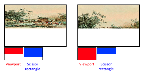
Scissors은 어떤 영역의 Pixel이 Framebuffer에 저장될지 여부를 정의한다. 그림 1은 Viewports와 Scissors의 관계를 보여준다. 그림 1의 왼쪽 부분은 Scissors가 Viewports보다 크다. 그래서 Rendering한 모든 이미지가 Framebuffer에 저장된다. 반면 그림 1의 오른쪽 부분은 Scissors 크기가 Viewports 보다 작다. 그래서 Viewports의 일정 부분만 Framebuffer에 저장된 것을 확인 할 수 있다.
MK: 위 그림을 기반으로 Scissors를 설명하면 Scissors는 Viewports의 불필요 한 영역을 제거하기 위해서 사용하는 것으로 판단된다.
우리가 작성하는 예제는 Scissors를 사용해서 영역을 제거할 필요가 없다. 그래서 Swap Chain 이미지와 동일한 사이즈로 설정한다. 코드 1-4는 Scissors를 설정하는 부분이다.
Viewports와 Scissors를 설정하면 VkPipelineViewportStateCreateInfo struct 에 저장하여서 정보를 하나로 합치는 작업을 수행한다. 코드 1-5는 VkPipelineViewportStateCreateInfo struct에 Viewports와 Scissors 값을 저장하는 부분이다. VkPipelineViewportStateCreateInfo struct은 아래와 같이 7개의 변수를 가진다.
VkPipelineViewportStateCreateInfo Struct (출처 7)
- sType (VkStructureType): 생성하고자 하는 Struct의 Type을 나타냄
- pNext (const void*): Extension Struct Pointer
- flags (VkPipelineViewportStateCreateFlags): 미래에 사용하기 위해서 미리 만들어 두었다고 함
- viewportCount (uint32_t): Graphics Pipeline에서 사용될 Viewport 개수
- pViewports (const VkViewport*): VkViewport(Viewport) Array 포인터
- scissorCount (uint32_t): Graphics Pipeline에서 사용될 Scissor 개수
- pScissors (const VkRect2D*): VkRect2D(Scissor) Array 포인터
VkPipelineViewportStateCreateInfo Struct에 필요한 정보를 모두 저장하면 Viewports/Scissors 설정이 끝난다.
Rasterizer
Rasterizer은 Vertex Shader에서 계산한 Vertex 값을 사용해서 Fragment Shader에서 연산이 필요한 Fragment(Color)를 찾는 과정이다. 예를 들어서 Vertex Shader에서 삼각형을 그리기 위한 Vertex Shader 연산을 완료하면 삼각형안에 들어가는 Fragment를 계산하는 과정이다. Rasterizer에서는 Depth Test, Face Culling 등 여러 가지 작업을 동시에 수행한다. Vulkan에서는 VkPipelineRasterizationStateCreateInfo Struct를 사용해서 Rasterizer 설정을 한다. 코드 1-6는 VkPipelineRasterizationStateCreateInfo Struct를 사용해서 Rasterizer을 설정하는 부분이다. VkPipelineRasterizationStateCreateInfo Struct은 아래와 같이 총 13개의 변수를 가진다.
VkPipelineRasterizationStateCreateInfo Struct (출처 8)
- sType (VkStructureType): 생성하고자 하는 Struct의 Type을 나타냄
- pNext (const void*): Extension Struct Pointer
- flags (VkPipelineRasterizationStateCreateFlags): 미래에 사용하기 위해서 미리 만들어 두었다고 함
- depthClampEnable (VkBool32): 해당 옵션을 Enable하면 Near/Far Plane을 벗어나는 Fragment도 Depth 값을 계산함 (Shadow Map등을 그릴 때 사용한다고 함)
- rasterizerDiscardEnable (VkBool32): Rasterizer 결과 Discard 여부를 설정함 (False 설정하면 모든 Fragment가 모두 Discard 됨)
- polygonMode (VkPolygonMode): Fragment가 생성되는 모양/방법을 나타냄 (크게 아래 3가지 방식이 있음)
- VK_POLYGON_MODE_FILL: Polygon안을 모두 Fragment로 생성함
- VK_POLYGON_MODE_LINE: Polygon Edge(선)만 Fragment로 생성함
- VK_POLYGON_MODE_POINT: Polygon Vertex 포인트만 Fragment로 생성함
- cullMode (VkCullModeFlags): Face Culling Type을 선택함
- frontFace (VkFrontFace): Vertex가 저장된 순서를 기준으로 앞면을 판단함 (Clock-Wise 또는 Counter Clock-Wise)
- lineWidth (float): 선의 굵기를 설정함
- depthBiasEnable (VkBool32): Depth 값을 계산하는 방법을 변경하기 위해서 사용함 (보통 Shadow Map을 그릴때 사용함)
- depthBiasConstantFactor (float): Depth 값을 계산하는 방법을 변경하기 위해서 사용함 (보통 Shadow Map을 그릴때 사용함)
- depthBiasClamp (float): Depth 값을 계산하는 방법을 변경하기 위해서 사용함 (보통 Shadow Map을 그릴때 사용함)
- depthBiasSlopeFactor (float): Depth 값을 계산하는 방법을 변경하기 위해서 사용함 (보통 Shadow Map을 그릴때 사용함)
VkPipelineRasterizationStateCreateInfo Struct에 변수를 설정하면 Rasterizer 설정이 끝난다.
Multisampling
Multisampling은 Anti-Aliasing(AA) 연산을 위해서 사용된다. 출처 9는 예전에 정리한 AA 자료이다. 간단히 설명하면 여러 개의 Fragment 값을 사용해서 Polygon Edge를 부드럽게 보이도록 하는 작업이다. 코드 1-7은 Multisampling Setting을 위한 코드이다. Multisampling 설정을 위해서 VkPipelineMultisampleStateCreateInfo Struct 에 필요한 값을 저장해야 한다. VkPipelineMultisampleStateCreateInfo Struct은 아래와 같이 9개의 변수를 가진다.
VkPipelineMultisampleStateCreateInfo Struct (출처 10)
- sType (VkStructureType): 생성하고자 하는 Struct의 Type을 나타냄
- pNext (const void*): Extension Struct Pointer
- flags (VkPipelineMultisampleStateCreateFlags): 미래에 사용하기 위해서 미리 만들어 두었다고 함
- pSampleMask (const VkSampleMask*): pSampleMask is a bitmask of static coverage information that is ANDed with the coverage information generated during rasterization, as described in Sample Mask.
- rasterizationSamples (VkSampleCountFlagBits): rasterizationSamples is a VkSampleCountFlagBits specifying the number of samples used in rasterization.
- sampleShadingEnable (VkBool32): sampleShadingEnable can be used to enable Sample Shading.
- alphaToCoverageEnable (VkBool32): alphaToCoverageEnable controls whether a temporary coverage value is generated based on the alpha component of the fragment’s first color output as specified in the Multisample Coverage section.
- alphaToOneEnable (VkBool32): alphaToOneEnable controls whether the alpha component of the fragment’s first color output is replaced with one as described in Multisample Coverage.
- minSampleShading (float): minSampleShading specifies a minimum fraction of sample shading if sampleShadingEnable is set to VK_TRUE.
현재 작성하고 있는 예제에서는 Anti-Aliasing 연산을 수행하지 않는다. 그래서 모든 부분은 VK_FALSE로 설정한다. VkPipelineMultisampleStateCreateInfo Struct 설명을 한글로 작성하지 않았다. 상세한 설명이 없어서 변수들이 정확히 어떤 용도로 사용되는지 모르겠다. 이 부분은 미래에 공부하게 되면 다시 정리할 예정이다.
Depth and Stencil Testing
Depth 및 Stencil Testing 연산을 하려면 VkPipelineDepthStencilStateCreateInfo Struct(출처 11)를 사용해서 설정해야 한다. 현재 작성하고 있는 예제에서는 Depth 및 Stencil Testing 연산을 수행하지 않기 때문에 NULL 값을 사용한다. Depth Testing 없이 모든 결과가 Framebuffer로 저장된다. Depth Buffering에 대한 설명은 다음에 작성할 예정이다.
Color Blending
Fragment Shader에서 Color(색상) 값을 결정하고 나면 값을 Framebuffer에 저장해야 한다. Framebuffer에는 기존에 계산된 Color 값이 저장되어 있을 수도 있다. 이 경우 기존 Color 값과 새로 계산된 Color 값을 사용해서 최종적으로 Framebuffer에 작성할 색상을 결정해야 한다. 이렇게 최종 색상을 결정하기 위해서 Color Blending Setting이 필요하다. Color Blending Setting을 위해서 2개의 Struct 을 생성해야 한다. 먼저 VkPipelineColorBlendAttachmentState Struct을 생성해야 한다. VkPipelineColorBlendAttachmentState Struct는 Attached되는Framebuffer의 개수만큼 생성을 해야 한다. 우리 예제의 경우 1개의 Framebuffer만 사용하기 때문에 하나의 VkPipelineColorBlendAttachmentState Struct 을 생성하면 된다. 코드 1-8은 VkPipelineColorBlendAttachmentState Struct 을 생성하는 부분이다. VkPipelineColorBlendAttachmentState Struct 는 아래와 같이 8개의 변수를 가진다.
VkPipelineColorBlendAttachmentState Struct (출처 12)
- colorWriteMask (VkColorComponentFlags): R,G,B,A 값 중 저장할 값을 표시함. 현재 작성하는 예제의 경우 R,G,B,A 모두 저장하도록 설정함
- blendEnable (VkBool32): Blending 연산 수행 여부. Disable시 계산된 결과값을 그대로 사용함. 현재 작성하는 예제의 경우 False로 설정함
- srcColorBlendFactor (VkBlendFactor): srcColorBlendFactor selects which blend factor is used to determine the source factors (Sr,Sg,Sb)
- dstColorBlendFactor (VkBlendFactor): dstColorBlendFactor selects which blend factor is used to determine the destination factors (Dr,Dg,Db)
- colorBlendOp (VkBlendOp): colorBlendOp selects which blend operation is used to calculate the RGB values to write to the color attachment
- srcAlphaBlendFactor (VkBlendFactor): srcAlphaBlendFactor selects which blend factor is used to determine the source factor Sa
- dstAlphaBlendFactor (VkBlendFactor): dstAlphaBlendFactor selects which blend factor is used to determine the destination factor Da
- alphaBlendOp (VkBlendOp): alphaBlendOp selects which blend operation is use to calculate the alpha values to write to the color attachment
Blending(blendEnable)을 False로 설정한 경우 srcColorBlendFactor, dstColorBlendFactor, colorBlendOp, srcAlphaBlendFactor, dstAlphaBlendFactor, alphaBlendOp값을 설정하지 않아도 된다. 그래서 정확한 설명을 정리하지 않았다. 역시나 계속 공부를 하게 되면 해당 부분에 대해서 추가로 작성할 계획이다.
VkPipelineColorBlendAttachmentState Struct를 생성하고 나면 VkPipelineColorBlendStateCreateInfo Struct를 생성해야 한다. VkPipelineColorBlendStateCreateInfo Struct는 Global Color Blending 설정을 위해서 사용된다. 코드 1-9은 VkPipelineColorBlendStateCreateInfo Struct를 생성하는 코드이다.VkPipelineColorBlendStateCreateInfo Struct는 아래와 같이 8개의 변수를 가진다.
VkPipelineColorBlendStateCreateInfo Struct (출처 13)
- sType (VkStructureType): 생성하고자 하는 Struct의 Type을 나타냄
- pNext (const void*): Extension Struct Pointer
- flags (VkPipelineColorBlendStateCreateFlags): 미래에 사용하기 위해서 미리 만들어 두었다고 함
- logicOpEnable (VkBool32): Bitwise Blending Operation(Bitwise Combination) Enable 여부. 현재 작성하는 예제의 경우 False로 설정함
- attachmentCount (uint32_t): 총 VkPipelineColorBlendAttachmentState(Attachment State) 생성 개수
- pAttachments (const VkPipelineColorBlendAttachmentState*): Attachment State Array 포인터
- logicOp (VkLogicOp): logicOp selects which logical operation to apply
- blendConstants[4] (float): blendConstants is a pointer to an array of four values used as the R, G, B, and A components of the blend constant that are used in blending, depending on the blend factor.
Global Color Blending 설정을 False로 선택하면 logicOp, blendConstants 변수값을 설정하지 않아도 된다. 이 부분 역시 미래에 공부하게 되면 다시 정리할 예정이다.
Dynamic State
보통 Fixed Function Setting을 변경하게 되면 Pipeline을 다시 생성해야 한다. 하지만 몇 가지 Setting의 경우 Pipeline을 다시 생성하지 않고 변경이 가능하다. 예를 들어서 Viewport 사이즈, Blending Constant, Drawing Line 사이즈를 변경 가능하다. 이러한 부분을 변경하기 위해서 Dynamic State 변수를 설정해야 한다. 우리는 변경할 계획이 없음으로 아무것도 생성하지 않고 NULL 값을 사용한다.
Pipeline Layout
Vertex/Fragment Shader에서 Uniform 변수를 사용할 수 있다. Uniform 변수는 Global 변수와 비슷한 개념으로 모든 Shader에서 참조 가능한 변수를 의미한다. 이러한 변수를 사용하기 위해서 Pipeline Layout을 생성해야 한다. 우리가 작성하는 예제에서는 Uniform 변수를 사용하지 않기 때문에 Empty Pipeline Layout를 생성한다. Dynamic State 등과 달리 Pipeline Layout은 Uniform 변수를 사용하지 않아도 꼭 생성해야 한다고 한다. 코드 1-10는 Pipeline Layout을 설정하는 부분이다. Pipeline Layout 설정을 위해서 먼저 VkPipelineLayoutCreateInfo Struct를 작성해야 한다. VkPipelineLayoutCreateInfo Struct은 아래와 같이 6개의 변수를 가진다.
VkPipelineLayoutCreateInfo Struct (출처 14)
- sType (VkStructureType): 생성하고자 하는 Struct의 Type을 나타냄
- pNext (const void*): Extension Struct Pointer
- flags (VkPipelineLayoutCreateFlags): 미래에 사용하기 위해서 미리 만들어 두었다고 함
- setLayoutCount (uint32_t): setLayoutCount is the number of descriptor sets included in the pipeline layout
- pSetLayouts (const VkDescriptorSetLayout*): pSetLayouts is a pointer to an array of VkDescriptorSetLayout objects
- pushConstantRangeCount (uint32_t): pushConstantRangeCount is the number of push constant ranges included in the pipeline layout.
- pPushConstantRanges (const VkPushConstantRange*): pPushConstantRanges is a pointer to an array of VkPushConstantRange structures defining a set of push constant ranges for use in a single pipeline layout. In addition to descriptor set layouts, a pipeline layout also describes how many push constants can be accessed by each stage of the pipeline.
Empty Pipeline Layout을 생성할 경우 위 변수들을 0 또는 Null로 설정하면 된다. 역시나 이 부분도 뒤에 추가로 설명할 예정이다. 앞 Fixed Function 설정과 달리 Pipeline Layout은 Struct 생성 후 vkCreatePipelineLayout(..) 함수를 사용해서 VkPipelineLayout Object를 생성해야 한다. vkCreatePipelineLayout(…) 함수는 아래와 같이 4개의 Parameter을 가진다.
vkCreatePipelineLayout(…) (출처 15)
- device (VkDevice): Logical Device 변수 (Create Logical Device에서 생성)
- pCreateInfo (const VkPipelineLayoutCreateInfo*): 앞에서 작성한 VkPipelineLayoutCreateInfo Struct 변수
- pAllocator (const VkAllocationCallbacks*): Pointer to custom allocator callbacks
- pPipelineLayout (VkPipelineLayout*): VkPipelineLayout Object를 저장할 변수
코드 1-11은 VkPipelineLayout Object를 생성하는 코드이다. VkPipelineLayout Object를 저장하기 위한 변수를 코드 1-12에 추가하였다. 이렇게 생성된 VkPipelineLayout Object는 vkDestroyPipelineLayout(…) 함수를 사용해서 제거를 해야 한다. 코드 1-13는 Pipeline Layout을 제거하는 부분이다.
Result & Conclusion
여기까지 설정하면 삼각형 하나를 그리기 위한 Fixed-Function 설정이 끝난다. 솔직히 작성해야 할 코드가 너무 많다. 그리고 대부분 Struct에 필요한 변수 값을 저장하는 정도라서 오타도 파악하기가 어렵다. 그래서 코드가 정확히 작성되었는지 여부를 판단하기는 더 어렵다. 출처 1에 따르면 이렇게 모든 Fixed-Function을 설정하면 Unexpected Behavior (예상치 못한 연산오류)등을 피할 수 있다고 한다.
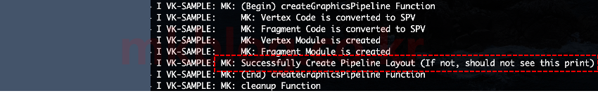
Pipeline Layout 부분에는 Object를 생성하는 코드가 있어서 컴파일 해서 실행한 화면을 그림 2에 첨부하였다. 위 코드는 출처 16에서 다운로드 가능하다.
출처
- https://vulkan-tutorial.com/
- https://www.khronos.org/registry/vulkan/specs/1.2-extensions/man/html/VkPipelineVertexInputStateCreateInfo.html
- https://www.opengl.org/sdk/docs/tutorials/ClockworkCoders/attributes.php
- https://alleysark.tistory.com/264
- https://www.khronos.org/registry/vulkan/specs/1.2-extensions/man/html/VkPipelineInputAssemblyStateCreateInfo.html
- https://stackoverflow.com/questions/42501912/can-someone-help-me-understand-viewport-scissor-renderarea-framebuffer-size
- https://www.khronos.org/registry/vulkan/specs/1.2-extensions/man/html/VkPipelineViewportStateCreateInfo.html
- https://www.khronos.org/registry/vulkan/specs/1.2-extensions/man/html/VkPipelineRasterizationStateCreateInfo.html
- https://mkblog.co.kr/2018/12/14/gpu-anti-aliasing-aa-ssaa-vs-msaa/
- https://www.khronos.org/registry/vulkan/specs/1.2-extensions/man/html/VkPipelineMultisampleStateCreateInfo.html
- https://www.khronos.org/registry/vulkan/specs/1.2-extensions/man/html/VkPipelineDepthStencilStateCreateInfo.html
- https://www.khronos.org/registry/vulkan/specs/1.2-extensions/man/html/VkPipelineColorBlendAttachmentState.html
- https://www.khronos.org/registry/vulkan/specs/1.2-extensions/man/html/VkPipelineColorBlendStateCreateInfo.html
- https://manned.org/VkPipelineLayoutCreateInfo/aa57d409
- https://www.khronos.org/registry/vulkan/specs/1.2-extensions/man/html/vkCreatePipelineLayout.html
- https://github.com/mkblog-cokr/androidVulkanTutorial